

European Rail Traffic Management System (ERTMS) is a European train control system that will be introduced onto the Great British Rail network over the next 30 years.
ERTMS is comprised of four main components.
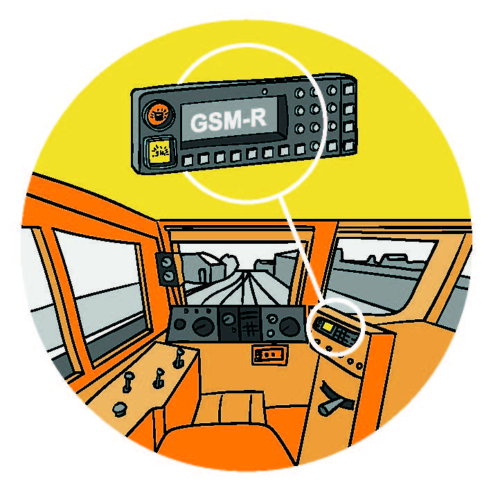
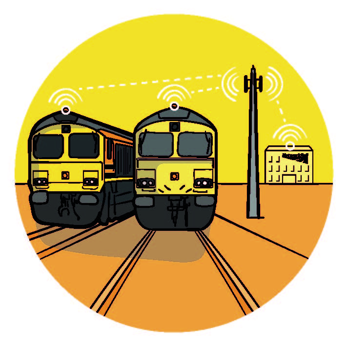
GSM – R Radio
Global System for Mobile Communication – Railway which is used as the transmission medium for in-cab data.
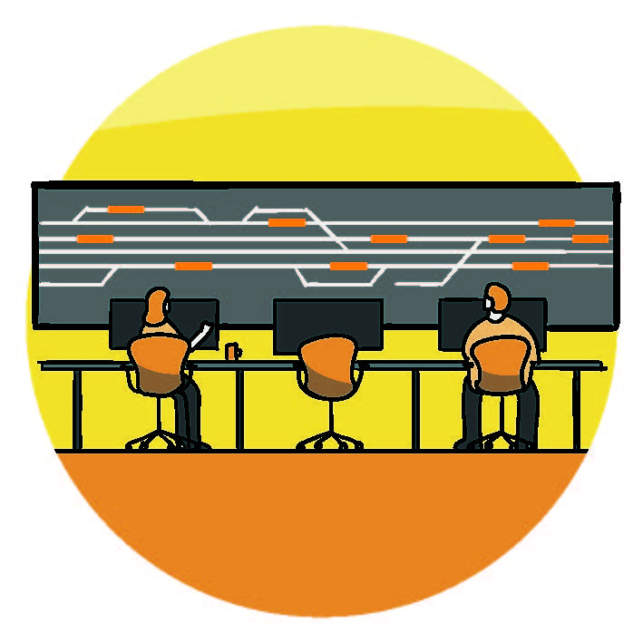
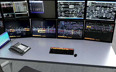
Traffic Management
An automated system which regulates train movement resulting in the improvement of network access and capacity
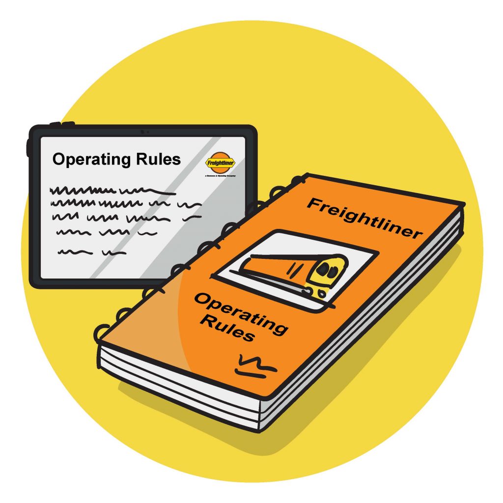
Operating Rules
A standard set of rules applied across the European rail network to provide a seamless multinational system.
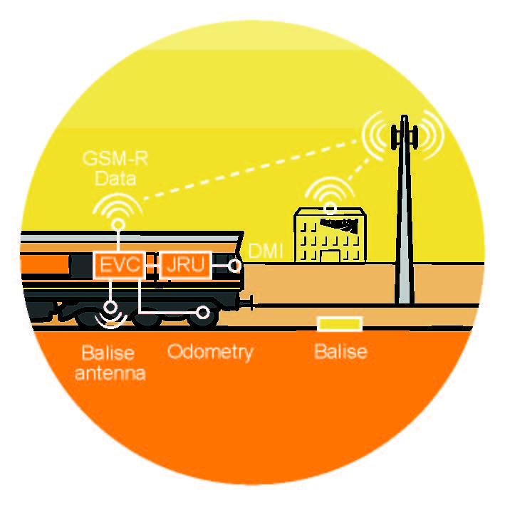
European Train Control System (ETCS)
The signalling and control component which works through the interaction of equipment fitted both trackside and on the locomotive, providing automatic train protection.
History of ERTMS in Europe
In the mid 1980s, the European Union Agency for Railways began to search for a common European operations system for the railways. This was to address the discrepancy in the way that individual European countries were running their railways. This included: accreditation for drivers, operating rules, cab communication systems and protection systems. All of the systematic variations made cross-border operations problematic and complicated. ERTMS was introduced to create a standard train protection system to enhance interoperability with regards to train operation and rules. ERTMS is deployed in 24 mainland Europe Countries and in isolated instances in Great Britain with expansion on the main network taking place now.
ERTMS Introduction in Britain
People and businesses from all over Britain rely on the current network. Freight and Passenger Train Operators compete for the best routes and time slots to meet their customers’ needs. New trains and services are being introduced, but there is still a lot of pressure on the current infrastructure. The challenge is that much of the current infrastructure was built over 200 years ago, during the Victorian times, and the method of controlling trains has not been significantly updated since then.
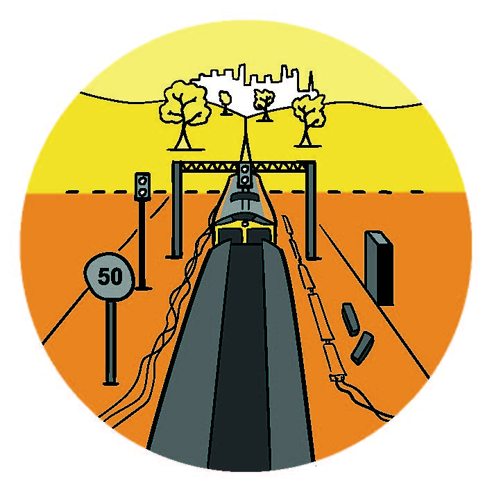
Currently, the way we operate the railway is limited by the size of the signaling block sections that make up the track. The UK is a mixed-use railway which means the track is shared between high-speed passenger trains and slow and heavy freight trains. In order to ensure safety on the railway, the number of trains permitted on a single block is fixed with the distance between each train based on the longest required braking distance. This is necessary because the system cannot differentiate between the different types of trains or their cargo. As a result, many trains are having to brake earlier than necessary and current signal spacing keeps trains far apart, particularly where a train is stopped in the section ahead, such as at a station.
With the introduction of the European Rail Traffic Management System (ERTMS), this can be improved. While being comprised of four components, the key one is the European Train Control System (ETCS). ETCS works by replacing conventional trackside signals with on board train control. An ETCS fitted Locomotive is able to continuously communicate with the track which will provide the driver with regular up to date information for them to control the speed and distance of their locomotive on the network. Through this, optimal use of the track can be achieved.
Benefits
Safety:
- Reduction in operational incidents through continuous live monitoring of the network
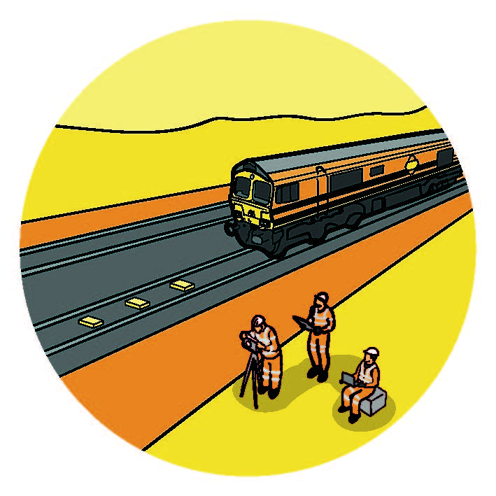
- Reduction in requirement for maintenance staff to be trackside
System Availability & Cost:
- Better train path utilisation and infrastructure availability
- Reduction in overall costs for renewal and maintenance
- Fewer infrastructure-based failures and therefore greater system and route availability
Environment through reduced carbon and greenhouse gas emissions:
- Removal of electrified lineside signals
- Greater fuel efficiency through optimised train acceleration and braking
User Operations :
- Automatic Train Protection (ATP), while in ETCS areas
- In-cab signaling provides continuous supervision, movement authorities and updates to the driver through the ETCS Displays
- Driver remains in complete control of the train, awareness and decisions supported by useful reminders
Have a Question?
How ETCS works
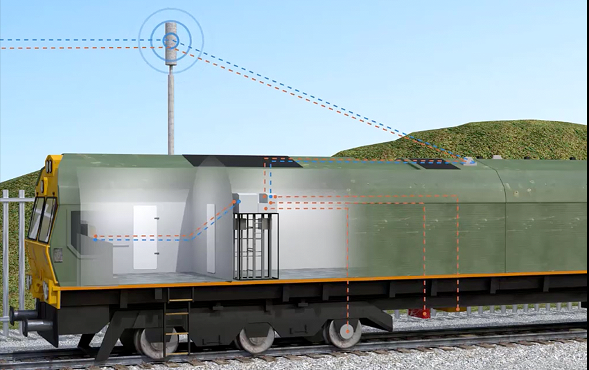
European Train Control System (ETCS) is divided into two core interacting systems: onboard and trackside. These components work by replacing conventional trackside signaling with in-cab indicators and ETCS Displays. Train speeds are continuously monitored by the system, making the railway safer. Drivers also have a planning area on the ETCS Displays which enables them to see a representation of the track for miles ahead. Over time, all trains operating over ETCS fitted routes will be fitted with train borne ETCS equipment.
ETCS works via technology fitted to the railway as well as components within the locomotives themselves.
Onboard ETCS Components
ETCS in Action
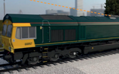
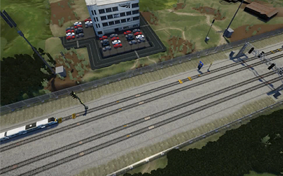
1.The Movement Authority (MA) is sent via GSM-R by the Radio Block Center (RBC) to the train’s EVC which updates the ETCS Displays. The driver stops the train at the End of Authority (EoA)
ETCS in Action
2.The signaller (or Automatic Route Setting) requests a forward route from the RBC. Providing it is available, the track interlocking confirms to the RBC that the requested route is available
ETCS in Action
3.The RBC sends an updated Movement Authority (MA) to the stationary train’s EVC. The EVC then updates the train’s ETCS Displays with the new MA
ETCS in Action
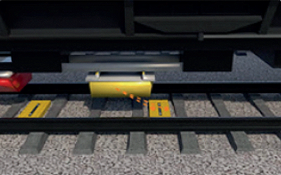
4.The driver moves forward and passes over a balise group which provides information to the train’s EVC
ETCS in Action
5.The exact location of the train is now confirmed on the train’s EVC, along with any other required operations information
ETCS in Action
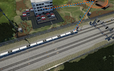
6.The EVC sends the train’s location to the RBC and the RBC updates the MA based upon track interlocking
Levels of ERTMS
ETCS is broken down into levels of operation depending on the status of the locomotive and railway it is operating on. This means that an ETCS fitted locomotive can run on both fully ETCS fitted parts of the network and areas still undergoing upgrades.
- Level – National Train Control (NTC) : An ETCS fitted locomotive moving on a non ETCS activated railway, will operate at national train control level. This means conventional signalling and TPWS and AWS equipment provide train protection.
- Level 2 (With Signals): Also known as overlay, this level takes place when ETCS is added to an existing signaling system. This allows a phased introduction to enable fitted ERTMS and non-fitted ERTMS trains to run simultaneously on a given line.
- Level 2 (Signals Away): Movement Authority (MA) is passed from the Radio Block Center (RBC) to the train and the train regularly sends its position information each time it passes over a Balise fitted in the track. This level provides continuous communication of train movements.
Maintaining an ETCS Fitted Fleet
The introduction of ETCS will necessitate an upgrade to Freightliner’s fleet of locomotives. The maintenance of the new system will be absorbed into the current vehicle Maintenance Plans. In a similar manner to current testing, the new components will require their own individual examinations and testing. These new procedures will be detailed in the newly updated Maintenance Plans. Staff will receive thorough and robust training on how to examine, maintain, fault find and rectify – look, book and fix.
Impact on Users
All drivers and fleet maintainers will receive mixed method training on the new equipment being fitted to trains. This will include classroom and applied training to all Train Drivers on how to drive ETCS fitted trains on conventionally signaled routes with AWS/TPWS. As ETCS fitted routes are activated, drivers will receive additional comprehensive training on how to drive ETCS fitted trains on these routes. Maintenance staff will receive their own bespoke training on how to maintain the newly fitted fleet. Training will include classroom and hands on opportunities to apply learnings in a simulated environment.
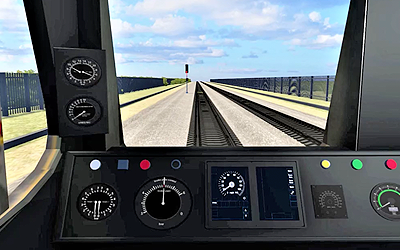
Driver Impact
Level NTC
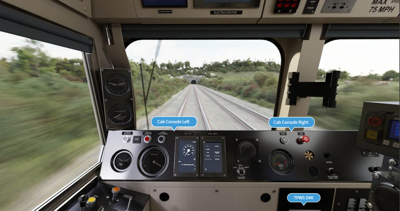
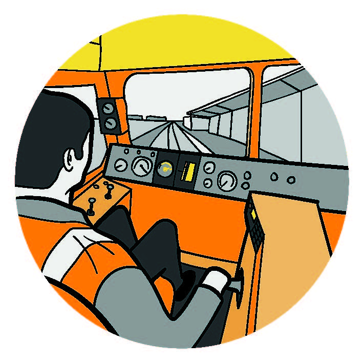
Given the time frame expected until ‘signals away’, the majority of drivers will only experience ERTMS level-NTC (National Train Control) for the remainder of their career. Level-NTC is the level given when an ETCS fitted locomotive is operating on the conventional TPWS/AWS signalling system. From a driver’s perspective, the main difference when driving a non-ETCS locomotive and an ETCS fitted locomotive will be the addition of some new equipment within the cab with the biggest change being the introduction of the ETCS displays. This new piece of technology will update the preparation procedure by requiring the driver to log in and enter details before mobilising. Additionally, the ETCS Displays will provide the driver with their current speed on the speedometer which is part of section 1 below.
Level 2
The biggest change to driving trains over ETCS fitted routes will be the way the driver receives information about the route ahead. On conventionally signaled rail lines, the driver receives this information at fixed railway signals which either show a green ‘Proceed’ aspect meaning the driver can continue at line speed until the next signal, a yellow ‘Caution’ signal, meaning proceed to the next signal but expect that signal to show a red, or a red signal which means ‘Stop’. Between these fixed points, the driver receives no indication of the availability of the route ahead.
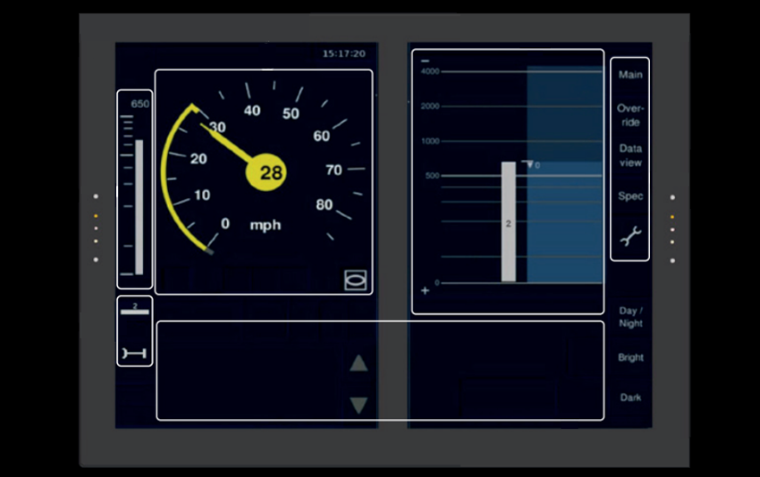
On an ETCS fitted route, known as level 2, the driver receives information via the ETCS Displays which are located on the cab desk. The ETCS Displays show the distance which the train has authority to proceed to, and the optimum speed which the driver should be travelling at. As the line ahead becomes clear, extensions to the trains authority are received by the train and displayed on the respected section of the ETCS Displays. In many cases, the driver could see that the line is clear and have authority to proceed for many miles ahead. This allows the driver to make informed decisions about the speed of the train and when and how hard to apply the brakes.
The ETCS Displays (Level 2)
Who’s involved
As an industry-wide change, the roll out of ERTMS requires the collaboration of all key stakeholders throughout the rail industry. Uniquely, this means Freightliner even working closely with its direct competitors for the benefit of the whole rail freight sector. Key stakeholders include:
- Network Rail
- Network Rails suppliers and partners
- Train Operating Companies (TOC’s)
- Freight Operating Companies (FOC’s)
- On Track Machine Operators (OTM’s)
- Charter & Heritage Operators
- Signalling system suppliers such as Siemens and Thales
- Original equipment manufacturers (OEM’s) such as train manufacturers/builders
- RSSB
- ORR
Within Freightliner, the ERTMS team is comprised of various experts from their fields. While each performs the responsibilities associated with their roles, collectively they assist with the introduction of ERTMS within the Great British rail network. As well as, safeguarding Freightliner’s interests, they also contribute towards protecting the interests of the freight sector and provide specialised knowledge and experience to the roll out of ERTMS.
To meet the ERTMS team members click here
