
Authored by the ERTMS Engineering Team
When the starter motors of a diesel locomotive are engaged by the driver, the battery voltage can drop by over 55%. The knock-on effects of this can cause the inside lights to dim for a few seconds. For sensitive electronics like ETCS, a sudden drop in voltage can be catastrophic.
So how do we prevent systems like this from failing?
Firstly, we need to carry out testing on some of the locomotives in the fleet to see exactly how much of a voltage drop we experience over time. To do this, we had to use a specialist instrument called an ‘Oscilloscope.’
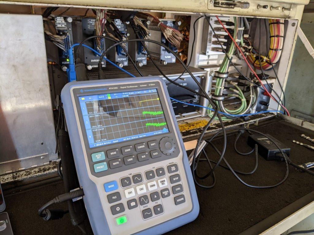
Normally, Oscilloscopes are used in laboratory environments, so we had to procure a special ruggedised unit designed for field use, as seen in figure 1. This unit is able to take a staggering 6,250 voltage samples per second!
Figure 2 below demonstrates what a 10 second snapshot looks like of a Class 66 engine starting. Yellow represents the voltage, and green is the amount of current drawn.

By analysing these graphs, we are able to determine how low the voltage dips are, and how long they last for. This is important because if the ETCS power system is not primarily designed for these voltage dips, the consequences are immense and can lead to power/equipment failure.
So will these voltage drops be more excessive after installing the ETCS equipment?
How can we measure this without installing the full suite of ETCS hardware?
The answer lies with a ‘DC Electronic Load’ pictured below in figure 3
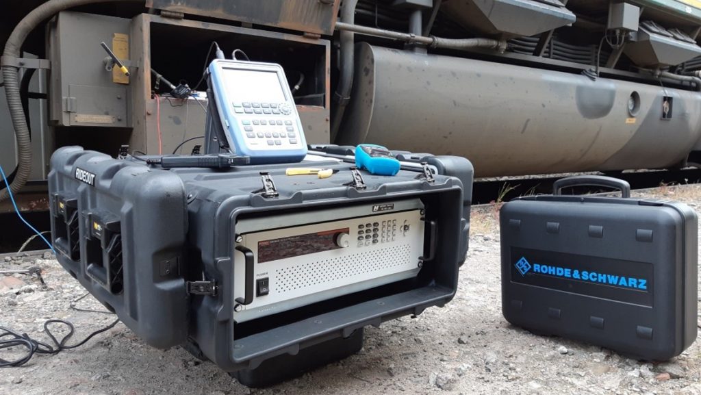
Much like Oscilloscopes, these are almost exclusively found in electronic labs. We were unable to source a rugged DC Load that met our test requirements, so our engineers had to design a protective enclosure for a laboratory unit. We settled on using a rackmount Pelican case, pictured in figure 4, typically found in military applications. This allowed us to take it directly to the locomotives and not worry about any sudden drops or moisture ingress.
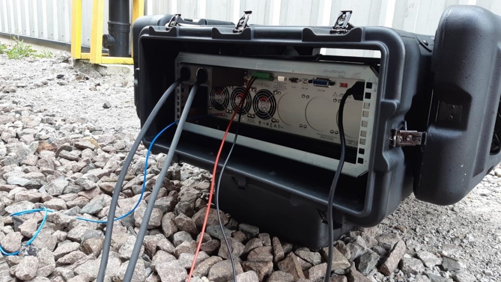
The thick cables on the back attach to the locomotive’s batteries. The unit can then pretend to be an ETCS onboard unit by drawing the same amount of power from the locomotive. This test will allow us to see how the vehicle will perform before the actual installation of the first locomotive.
All the data captured from this testing has allowed the engineers to design a resilient power supply system for ETCS that will keep working throughout all the different operational scenarios of the fleet.
If you want to learn more about Power Testing or raise a query to the engineering team, please contact your local Maintenance Specialist or drop us an email at ERTMS@gwrr.co.uk.
